Sunday, May 13, 2018

Throttle Body adapter and TPS adapter details

For those who have asked, here is a quick sketch of the injector adapter. I made four of these out of delrin, which would work just fine. Let me know if you are interested in them, you pay shipping.
The groove at base of small diameter is for a 1/8"x 1" dia "O-ring" to seal the cap in throttle body. I used Bosch injector out of a 2.0L Mazda junkyard engine. So your bore must accommodate that size injector.
Here you see the adapters with injectors. Note the retainers made from original domes.

This shows #2 throttle body with shaft drilled and tapped, tang in place and ring made from 1" emt conduit. Picture below shows some of the notching needed to fit on TB.


The picture above shows nuts have been added to the ring and the whole assembly has been JB Welded to the TB. I used a 90's era Honda TPS. You will want to make sure your TPS will fit the ring assembly. Pay attention to the hold down screw locations.

Saturday, September 19, 2015

2.5 " 36-1 crank wheel, worth the money, $75

 Decided to use a Ford EDIS ignition. Here you see the crank sensor mounted on TB cover.

Extruded aluminum fuel rail, about $25 for 12". Just enough to do the job.

Painted timing marks on cam wheel, on the money. EDIS runs timing at 10 degrees BTDC. Be certain to install trigger wheel and sensor correctly.

Has been a while since my last post, good news is I just got the FI running after a long delay. Here are some pictures.
 This is what the throttle bodies looked like in mockup.
 Bottom side of carbs with everything ground off.


 Using stock linkage, chokes have been decommissioned.


 These I had originally made out of a plastic, later had them fabbed of aluminum.


 TPS needed a place, drilled the throttle shaft, tapped it, then added a lever. Used a bit of conduit to make the housing, welded a couple of nut to hold retaining screws. A little JB weld, viola!!.

 Ready  for paint.


 I started out using injectors and fuel rail from a 2.3L mazda. Ended up purchasing aluminum fuel rail because it is easier to work. Kept the HI Z injectors.

 Vacuum ports on the bottom side.


So this is where I hope to go, low pressure turbo with FI.
 

Saturday, September 6, 2014

As of September 2014 the FI is in this state, mounted on the GL1000, ready for electronics. There were a number of adjustments I had to do in order to fit everything in place. That said, you must realize that fitting is a part of this kind of customization, so be not afraid, just make sure you maintain the structural integrity of the frame. When I began this project I spent some time reinforcing the frame just for this purpose.


 Right side showing fuel pressure regulator, fuel rail, injectors and plugs that injectors fit into.
 Front view showing throttle position sensor and wiring harness.
 Left side, fuel rail. I had to use a couple of  3/8" nuts as spacers to move left stiffener forward to clear TPS, at left.
 Looking down, front is to left. Note that I removed the cross bar to clear for fuel crossover tube. Also note, I removed bottom half of the two gussets. One is visible over the pressure regular, it is close, but does not touch.
 Looking from right side of bike you can see where left fuel rail clears the left side gusset.
 Here you see the pressure regulator, having had the fuel rail shortened and the mounting flange rotated to clear frame where lower half of gusset was removed.
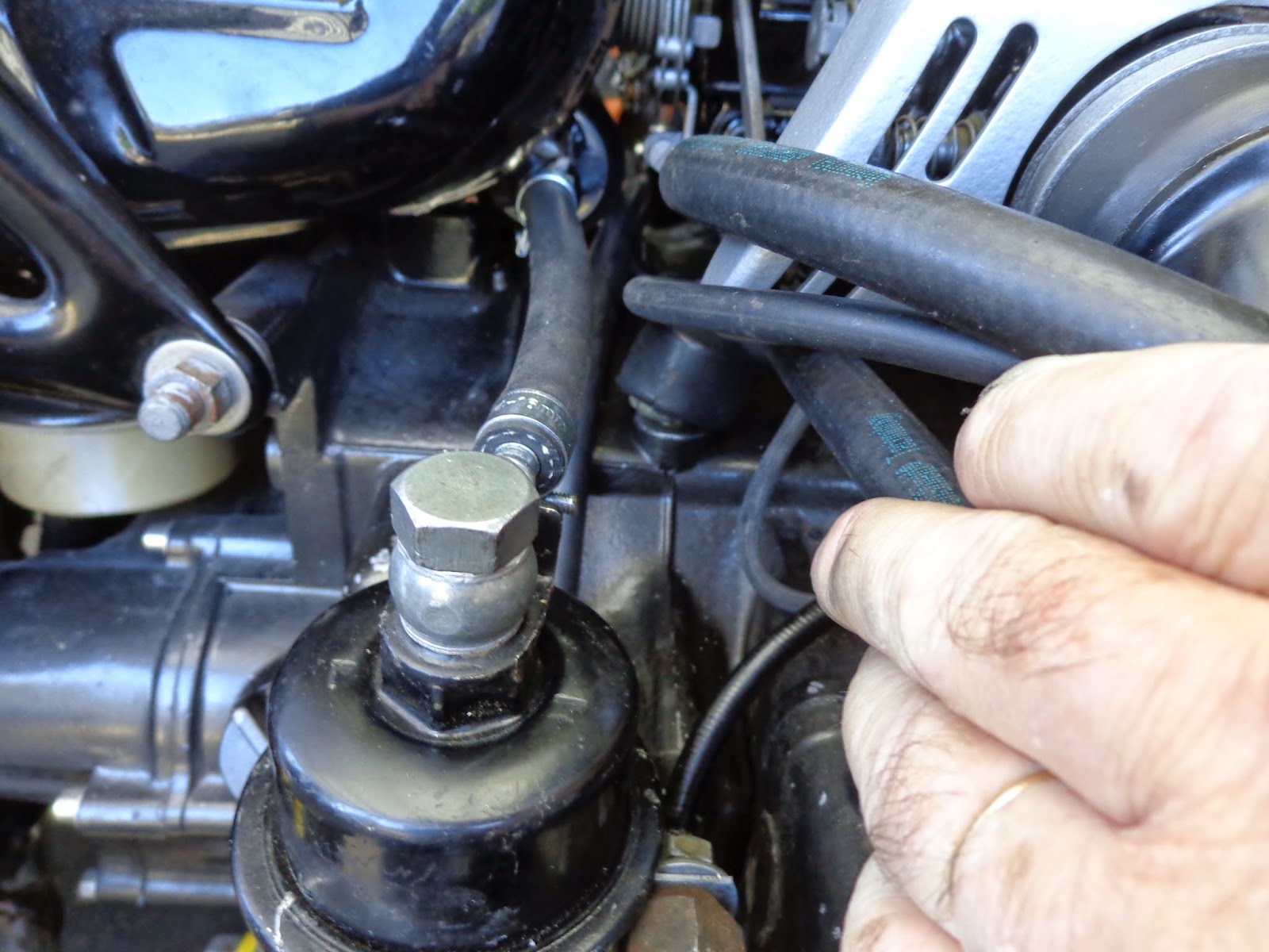
 Fuel filter mounted where mechanical pump used to reside
Left side showing external fuel pump mounted under tank. I may do an in-tank fuel pump at a later date.

Fuel Injection Install

This installment shows the FI as of September 2014, there was some adjustments that had to be made to get it all in as planned. Aside from a couple minor issues, I am pleased with the look of the thing. I hope to have it running in a couple of weeks, given availability of time to work on it.

Here we have the induction viewed from the right side, I had to shorten the fuel rail in the foreground and re orient the pressure regulator to fit in the space allowed, this includes removing the bottom half of the gussets at the rear cross member. Nothing a visit to Harbor Freight can't solve. Bear in mind that I had done extensive frame reinforcements in the early stages of bike construction, just for this reason. I do not recommend removing structure without compensation.

 This view is from the front, TPS is visible as well as the wiring harness.
 View from left side of bike.
 Looking down , front is to left.


Thursday, August 21, 2014

Fuel injection for the YellowJacket

It has been some time since I last made a post, so here's a new one. When I first did the build on the YellowJacket, I had installed the fuel injection setup from an '85 GL1200. It worked alright, but I did not care for the look of it. A little too commercial plumbing if you know what I mean. So I got a hold of a retired set of stock carbs, gutted them, had some plugs, fabricated, plugged up all the leaky stuff, and set up some fuel rails. I will be using a Mega Squirt ecu, running timing and fuel. Eventually, it will have a turbo installed, but I figure it would be best to get the FI nailed down before I blow it up.
Here are some pics.


 Above are the bodies after being milled flat and
mounted on the airbox.


At right are the injectors from a 2.0 Mazda, and the plugs made to fit inside the piston bore. The recess for the injectors is angled at approx. 45 degrees, which points down stream toward the head. I recycled the dashpot portion with bolt tabs as retainers for the plugs.


I made a TPI mount by drilling and tapping the throttle shaft of #2 carb. A little JB weld and a bit of thin wall and I have a place for the TPI to live.


You can see the TPI in this picture.


At first I thought I could use the fuel rail that came with the injectors, why not! The spacing was perfect and I had them in hand. If I would have brazed them, it would have been OK. As it was, they were not going to fly, so I bought some brass fittings and a piece of fuel rail and made a stronger system. These pictures show the first fuel rail setup.


I needed to have  an Idle air circuit as well as vacuum /pressure port for the eventual turbo setup. you can see the intake air temp sensor in the middle of the air box.
Did I mention turbo? Just so happens, I got a T15 online with wastegate, so I welded this thing up. I have removed the center stand and have put together plumbing to fit this thing under the bike in the space vacated by the center stand.